Video: HDMI without a video chip
The board’s HDMI socket is wired directly to the RP2040’s pins. No graphics chip: software builds the signal, 270 million bits per second for each colour.
On this page
The signal to produce
An HDMI screen accepts DVI, its simpler ancestor: three wire pairs for red, green and blue, and one pair for the clock. Each pixel of each colour is sent as a 10-bit symbol, known as TMDS. For a 640 × 480 screen at 60 frames per second, that makes 252 million bits per second on each pair.
Eliott65 first set the RP2040 to 252 MHz: one bit per cycle, exactly. Since v0.52, the signal is 720 × 480 at 60 Hz and the RP2040 runs at 270 MHz (see below): still one bit per cycle.
How the driver goes about it
- The PIO serialises. A two-instruction PIO program sends the bits one by one on each pair, and a third builds the clock.
- The DMA feeds it. For each colour, DMA channels send the words of the line and chain themselves from one line to the next (two channels per colour at first, three since v0.46, see below). No core needs to step into the stream.
- No frame in memory. A 640 × 480 image would take hundreds of kilobytes. The driver only keeps two line buffers, already encoded, and three constant sync lines: about 14 KiB in all in the first version. While one line is going out, the next is being prepared.
The logical image is 320 × 240 pixels, doubled in both directions. Each logical line must therefore be ready in 63.5 µs, the time of two screen lines.
The “zero-copy” text screen
In text mode, the screen is 40 × 30 characters. The 6502 program tells the kernel where, in its own memory, its characters are; the video driver reads them there directly, on every frame. No screen buffer is reserved: a program that displays nothing does not lose a single byte.
A variant adds an attribute page: one byte per cell, giving the text colour and the background colour from 16 colours. To animate a rainbow title, the demonstration only rewrites 15 attribute bytes on each beat.
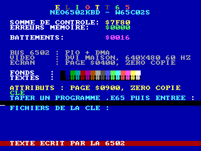
The puzzle of the wrong colours
First display: the blue background is right, but the white text comes out light blue, a white line appears on the right, and on the colour-bar test pattern the screen loses sync altogether.
The checks rule out the leads one by one: the buffers actually sent, read back through the debug probe, are correct; so is the polarity (an inversion would have given a yellow background); a bit shift is ruled out by calculation; reducing the output drive strength changes nothing.
The cause: to get each colour exactly, the symbol table chose, for white, symbols that
alternate on every bit (0101010101), i.e. a 126 MHz signal. The board’s link carries it poorly;
on a large white area, the screen loses the signal.
The fix: choose symbols with as few transitions as possible (5 at most instead of 9), even if
that means being off by 2 levels out of 255. White becomes 1011111111 then 1000000000. Correct
display, confirmed on screen.
From DVI to real HDMI (v0.44 – v0.46)
DVI only carries the picture. HDMI adds data islands in the sync intervals: the description of the picture mode, and sound. To code them, the project read two independent open implementations (hdl-util/hdmi and ikjordan’s PicoDVI-HDMI) without reusing any of their code, and the emulator’s video bench became an HDMI receiver that checks every packet.
- v0.44: one island per frame describes the mode (640 × 480, 4:3); 65 frames per second, no late line on the board.
- v0.45: “stable” on the user’s screen; HDMI becomes the default mode.
- v0.46: to be able to place an island on every screen line (not on every logical line, which is sent twice), the DMA is redesigned: three channels per colour, including a ring of line endings that advances by itself. The 525-line list goes away, freeing about 2 KiB.
The sound carried by these islands is told in Sound.
Faster text (v0.47)
Sound took a little of core 1’s time, and the text mode’s margin had dropped to 1 µs. Text rendering was rewritten: characters and attributes read once per line instead of three times, pixels chosen without branching. 61 → 50 µs per line.
One signal: 720 × 480 at 270 MHz (v0.50 – v0.52)
The Hercules mode needs 720 pixels across. First step (v0.50): a 720 × 480 at 60 Hz signal, the format of television video modes (CEA-861), with a 270 MHz system clock (10 × 27 MHz). It is the signal the Trinity project had validated on this board and this screen. On the board: picture “stable” according to the user, no late line.
One question remained: this signal for the Hercules mode only, or for everything? The user chose “all in 720” (decision 0027):
- one signal for every screen mode; the clock stays at 270 MHz from power-up to shutdown, never changing on the way, so there is no bus, timer or PIO to re-tune;
- the 320 × 240 modes (text and graphics) keep their 640 × 480 picture in the centre, with 40-pixel black borders;
- the 6502 runs 9% faster, and each line gets 7% more cycles to be rendered.
HDMI in 720 (v0.51). The data island (38 useful words) does not fit in a 31-word horizontal sync. It starts with the sync and overflows by 7 words into the following porch; each character of the island then carries the sync level of its position. On the bench, the simulated receiver counts 1,050 correct packets and a sync left intact across the island; on the board, the picture stays stable. By default (v0.52): 720 × 480 becomes Eliott65’s signal; the old 640 × 480 remains a build option.
The move to 270 MHz came at a price on the 6502 bus: see The bus.
The Hercules mode (v0.53 to v0.60)
The Hercules mode follows the spirit of the monochrome cards of the first PCs: 720 × 350 pixels at 1 bit per pixel, with white, amber or green ink. Like the text and the graphics, the image (31,500 bytes) is read directly from the 6502 program’s memory, without copying: the program draws with plain writes. The 350 lines are centred in the signal’s 480.
- An encoding chosen for exactness. Black and each ink level have a TMDS symbol that is balanced on its own (as many 0s as 1s): any two neighbouring pixels can be encoded in one word, and a 16-entry table per colour encodes 4 pixels in 2 words. The picture produced on the bench is exact (a difference of 0, against 2 levels in the other modes, see the colour puzzle above).
- No line doubling. Each screen line has its own content: core 1 prepares the next line while the current one goes out. The mode is frozen at the start of each frame.
- Memory counted out. With 720, the firmware’s memory was nearly full (504 bytes free). A few savings (useless program-exit code, smaller arithmetic routines, tables stored with the font) freed enough for the mode: 352 bytes remain.
- The
HERCULE.E65demo draws a frame, a diagonal and a checkerboard in amber.
The 80 × 25 text (v0.54). The mode also has its text screen: 80 columns by 25 rows, in 9 × 14 pixel cells. As with ordinary text, the characters are read without copying from the program’s memory, with an optional attribute page: inverse, underline, blink.
- A provisional font at first: the project’s 8 × 8 font (public domain), stretched over 11 of the cell’s 14 lines.
- More memory to find. 976 bytes were missing. The hibernation header is now partly written from a page of zeros in the kernel, and line endings are produced by the interrupt instead of being copied: 532 bytes remain free. On rereading, a copy of the font by 32-bit words was turned back into a byte-by-byte copy: it assumed an alignment nothing guaranteed, and the RP2040’s processor would have stopped.
- The
HTEXTE.E65demo shows a title in inverse, an underlined line, a blinking word, the character table and an 80-column ruler, in green.
A font drawn for Eliott65 (v0.58). The published capture of the original MDA font is under CC BY-SA 4.0, a licence the project’s EUPL 1.2 does not list among its compatible licences: it was not used. The project therefore drew its own 9 × 14 font, under the EUPL 1.2:
- 95 characters, from space to tilde, on 7 columns; the 8th and 9th stay blank to separate the
characters. Capitals take lines 2 to 10, lower case 5 to 10, and descenders (
g j p q y , ;) go down to lines 11 and 12. - A source that can be read and edited: a text file where each character is drawn in
#and., from which a tool produces the firmware file. Tests check that every character exists, that the margins are respected and that the baseline is shared. - The font (1,344 bytes) is copied from flash into memory when switching to Hercules text; 4,308 bytes of firmware RAM remain free.
The shell in 80 columns (v0.57). The MODE 80 command switches the shell to 80 × 25 Hercules
text, in white, without attributes; MODE 40 brings it back to 40 × 30 colour. See
Multitasking.
On the board: too slow (v0.59), then sped up (v0.60). Measured on the board, both Hercules modes overrun their budget. Each line is prepared while the previous one is sent: the budget is 31.75 µs, half that of the 320 × 240 modes, where one logical line covers two screen lines.
| Mode | Rendering one line (at most) | Late lines, per frame |
|---|---|---|
| 40 × 30 text (shell) | 46 µs, for 63.5 µs | 0 |
| 80 × 25 Hercules text | 64 to 65 µs | about 126 out of 350 |
| Hercules graphics | 37 µs | about 321 out of 350 |
A late line goes out unfinished, and its end may show the content of the line before; this was not seen, for lack of a visible screen. The emulator’s bench checked for an exact picture, but not for time: the board revealed the fault. The cause is the cost of encoding: the graphics write 1,080 words per line, and the budget requires fewer than 8 cycles per word.
v0.60 rewrites the encoder in assembly, shared by graphics and text (two reads and one 4-word write per byte and per lane), and reads a text row only once for its 14 lines. A new tool stops rendering on chosen lines and compares what the board really encodes with the expected picture. This is not yet checked on the board; 3,640 bytes of RAM remain free.
Sharing with the bus
The video and the 6502 bus both use the DMA. Turning the video on took the 6502 from 7.52 to 7.38 MHz (measured at 252 MHz): the price, about 2%, of a picture without a frame buffer.
Checking without a screen
A tool reads back, through the debug probe, the line buffers actually sent, decodes them, and rebuilds the expected image from the 6502’s text page. A diagnostic test pattern (8 bars, then red, green, blue and grey ramps of 16 steps) was validated from a photo. In the emulator, a test bench runs the real driver and a simulated screen decodes its output: 0 pixels differ from what is expected. See The emulator and the test benches.
What about graphics?
Since version 0.27, the driver also displays tiles and sprites at 320 × 240. The challenge is then to keep within the 63.5 µs per line; that is the subject of the article Tiles and sprites.